![[NAAPO Logo]](../../NAAPOsm.jpg)
|
Argus The Next Generation Radio Telescope |
|
Argus The Next Generation Radio Telescope |
|
STATUS REPORT ON ANTENNA DEVELOPMENT
By Brian Baertlein 07/02/1999
The design of an antenna array for the Argus system poses a number of
engineering challenges, but based on work reported below we are confident
that an acceptable array can be fabricated with our proposed resources.
The goal of this sub-task is to construct a 64-element array to operate in
the frequency range 400 MHz to 2 GHz with a VSWR of at most 2:1. A highly
uniform pattern over a hemisphere is desired in this band, with a null on
the horizon. To achieve the lowest possible noise temperature, the antenna
should have negligible backlobes, and lossy components must be avoided. In
our initial work we have considered elements that are sensitive to a
single polarization, but (as we show below) the extension to fully
polarimetric operation is not a problem. The geometry of the array is
intentionally unconstrained; it should be sufficiently flexible to support
experiments into novel imaging concepts. Finally, we require a low
fabrication cost (<$ 2k for the array) and the ability to easily
manufacture the elements in quantity.
In a previous effort [1] OSU employed an antenna array comprised of
bent dipoles arrayed over a ground plane. Based on a design by Lin [2],
that array has the remarkable ability to exploit mutual coupling between
elements to improve its performance. Measurements performed with an
antenna designed for operation at 1.5 GHz showed many attractive
characteristics. The performance of the bent dipole array, however,
is closely linked to its periodic, rectilinear geometry. To achieve
more flexibility in array geometries an investigation of alternative
designs was initiated.
Since the mid-1950s there has been intensive investigation of wideband
antenna concepts for several applications, including electronic
intelligence (ELINT), electronic countermeasures (ECM), and measurement
of electromagnetic interference (EMI). For radio astronomy applications,
among the most attractive of these concepts is the planar spiral. First
described in a 1959 paper by Dyson [3], the two-arm logarithmic
(equiangular) spiral is a self-complementary structure, for which very
wideband operation is possible. These balanced antennas are capable of
VSWRs below 2:1 over a decade of bandwidth. Spirals exhibit circular
polarization with axial ratios better than 1.5:1 on axis, the sense of
the polarization being determined by the sense of the spiral winding.
They are also known to exhibit weak mutual coupling [4]. The Archimedean
spiral, with a linear (rather than exponential) rate of expansion, is not
truly frequency independent, but it has very similar properties and is
easier to manufacture.
A significant limitation of spiral antennas for radio astronomy
applications is that they are bidirectional. It has long been known,
however, that by placing a ground plane one quarter wavelength behind
the antenna one could obtain unidirectional radiation at the cost of a
severe reduction in bandwidth [5]. An important contribution was made
by Wang and Tripp [6,7] who showed that the presence of the ground plane
is compatible with the desired antenna current distribution, although it
tends to enhance the contribution of currents reflected from the spiral
terminations. Moreover, they found that performance was not a strong
function of the antenna-ground plane separation, provided the separation
was a quarter wavelength or less. They were able to construct antennas
with 10:1 bandwidth by using a resistive loading to attenuate those
reflected waves.
Through a combination of simulations and experiments we have found that
a spiral over a ground plane without resistive loading has roughly a
factor of two reduction in bandwidth (at the lower end) with respect to
a loaded spiral of the same design. Since the lower bandwidth is directly
proportional to the outer circumference of the spiral, one can achieve a
bandwidth comparable to that of a loaded spiral (but with lower noise
temperature) by doubling the diameter of the unloaded antenna.
A prototype spiral antenna for the band 400 MHz to 2 GHz was built and
is shown in Figure 1. This element was constructed with 3/8" O.D. copper
refrigeration tubing and has a diameter of roughly 60 cm. The tubing is
held to a dielectric substrate with inexpensive tie-wrap mounts. The total
cost of the antenna components is roughly $30. The antenna is placed
roughly 5 cm above a ground plane and is fed through a wideband tapered
coaxial balun [8]. The impedance bandwidth of the antenna is apparent
from the VSWR measurements shown in Figure 2, where we find VSWR<2.2
over most of the desired band with especially good performance near the
critical 1.4 GHz hydrogen line. Below 400 MHz the length of the antenna
limits performance. Above 2 GHz, the details of the feed construction are
significant. The pattern of the antenna was measured by receiving GPS
signals over a period of 3.5 hours as described in [1]. The resulting
data are shown in Figure 3, where we have plotted the apparent position
of the GPS satellites during the measurement period. Detection strength
(on a linear scale) is color-coded. The results show a very smooth pattern
over much of the hemisphere, as desired.
Several issues must be examined to complete the design work. We have
an interest in improving the VSWR, particularly in the region of the
hydroxyl line at 1.7 GHz. Performance at the upper end of the band
depends on the antenna design near the feed, which is in turn
constrained by the balun dimensions. We are presently redesigning the
balun. Although our current design has a very wide bandwidth, it is
based on a physically large coaxial line and it is difficult to construct.
An alternative design based on surface-mounted wideband transformers has
been developed and is now being fabricated. The cost of the components,
circuit card, and connectors is estimated to be less than $10/antenna.
Although these antenna elements have been developed with a flexible
array geometry in mind, it remains to develop some useful array
configurations and to verify the performance in such configurations. We
are currently exploring dense array concepts, in which smaller replicas
of the spiral are packed in voids between larger spirals, leading to
reduced grating lobes over wide bandwidths. Arrays for fully polarimetric
sensing can be constructed by using spirals wound in both directions.
These concepts are also being studied.
|
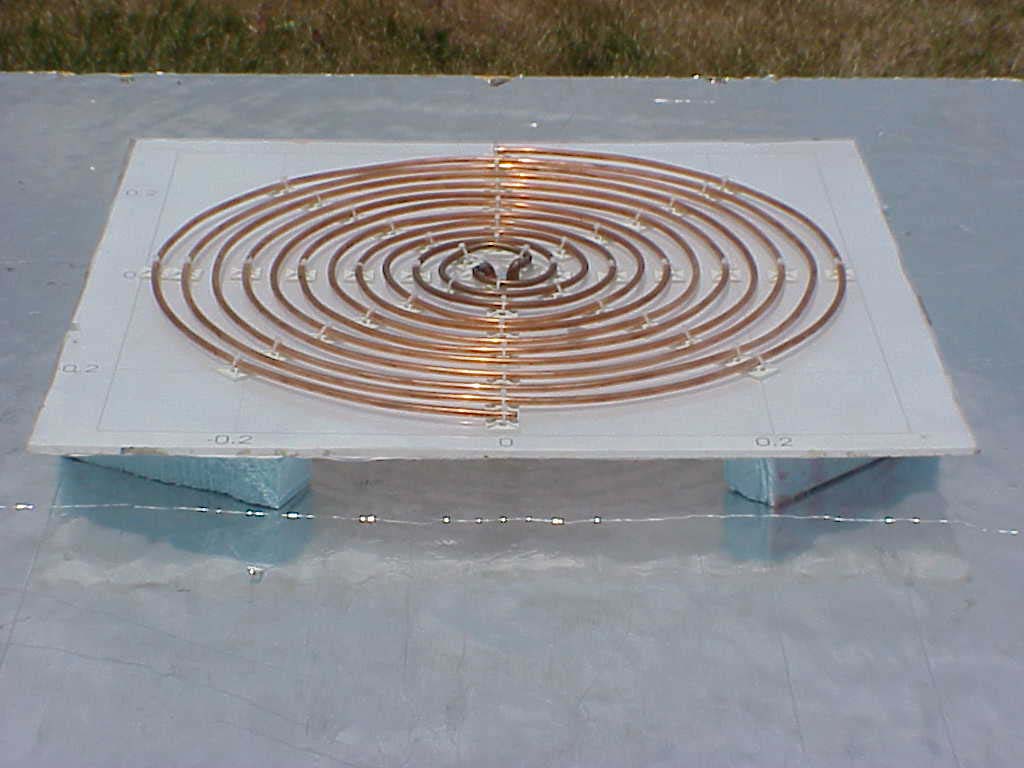
| Figure 1. The prototype planar spiral antenna. The antenna is operated over a ground plane with 5 cm spacing. The feed is attached from the back side via a wideband balun. (Click on photo to view larger image.) |
| Figure 2. VSWR measured for the planar spiral over a ground plane. (Click on photo to view larger image.) |
| Figure 3. Reception of GPS satellites by the planar spiral over a ground plane. The measurements were performed over a duration of roughly 3.5 hours. The blue circle indicates the horizon. (Click on photo to view larger image.) |
|
References
[1] S. W. Ellingson and R. S. Dixon, The OSU Omnidirectional Radio
Telescope Project, OSU ElectroScience Laboratory Technical Report 531393-1,
Jan 1999.
[2] S. J. Lin, On the Scan Impedance of an Array of V-Dipoles and the
Effect of the Feedlines, Ph.D. Dissertation, The Ohio State University, 1985.
[3] J. D. Dyson, "The equiangular spiral antenna," IEEE Trans. Antennas
and Propagat, pp. 181-187, April 1959.
[4] J. D. Dyson, "The coupling and mutual impedance between conical
log-spiral antennas in simple arrays," 1962 IRE International Convention
Record, Part 1, pp. 165-182.
[5] H. Nakano, K. Nogami, S. Arai, H. Mimaki and J. Yamauchi, "A spiral
antenna backed by a conducting reflector," IEEE Trans.Antennas and
Propagat., AP-34(6), pp. 791-796, June 1986.
[6] J. J. H. Wang and V. K. Tripp, "Design of multioctave spiral-mode
microstrip antennas," IEEE Trans. Antennas and Propagat, AP39(3),
pp. 332-335, March 1991.
[7] J. J. H. Wang and V. K. Tripp, "Multioctave Microstrip Antenna ",
US Patent 5,313,216, May 17, 1994.
[8] J. W. Duncan and V. P. Minerva, "100:1 bandwidth balun transformer,"
Proc. IEEE, Vol. 48, pp. 156-164, Feb. 1960.
|
| HOME | FEEDBACK |
|
Copyright © 1996-2001 Big Ear Radio Observatory and North American
AstroPhysaical Observatory. Originally designed by Point & Click Software, Inc. Updated by Jerry Ehman. Last modified: 12/3/2001. |