![[NAAPO Logo]](NAAPOsm.jpg)
| NAAPO (North American AstroPhysical Observatory) |
| The First Argus Radio Telescope By: Dr. Jerry R. Ehman August 5, 2002 |
|
Notes to the Reader: This article was written by Dr. Jerry Ehman. It is based on the 1988 Master's Thesis entitled: A Simultaneous Multi-Beam Phased Array Using Digital Processing Techniques written by James L. (Jim) Bolinger, in partial fulfillment of the requirements for the degree Master of Science in the Graduate School of the Ohio State University (OSU). Jim acknowledges Dr. John D. Kraus and Dr. Robert S. (Bob) Dixon, Director and Assistant Director, respectively, of the Ohio State University Radio Observatory (OSURO), for their guidance on the project. Dr. Kraus was a member of the Master's Examination Committee. Dr. Dixon originated the fundamental concepts for this radio camera project. Jerry Ehman wrote this article to show the connection between the radio telescope (radio camera) designed, built, and operated by Jim Bolinger for his Master's Thesis and the Argus-type telescopes that have been built since and are currently being built, both by Dr. Steven Ellingson at the Ohio State University ElectroScience Laboratory (ESL) and by radio observatory volunteers under the auspices of the North American AstroPhysical Observatory (NAAPO). All illustrations in this article may be viewed in a larger size by clicking on each illustration. Then click on the Back button or use Alt+left arrow to get back to this page. |
|
According to Jim Bolinger (private communication; 5/9/2002), the first
use of the term Argus used for a scientific device occurred in
the 1975 book by Arthur C. Clarke entitled Imperial Earth.
Jim told me that he was aware of the Greek mythology behind the name Argus,
namely that Argus was a guard being having 100 eyes and could see in all
directions at once. Tom van Horne, a volunteer with the Radio Observatory,
also was aware of Argus in Greek mythology and mentioned it to Bob Dixon.
Jim and Bob Dixon discussed this mythology and Bob decided to use the
name Argus for his concept of a radio telescope that could detect signals
('see') in all directions at once (i.e., over a hemisphere since no
radio waves could penetrate through the center of the earth).
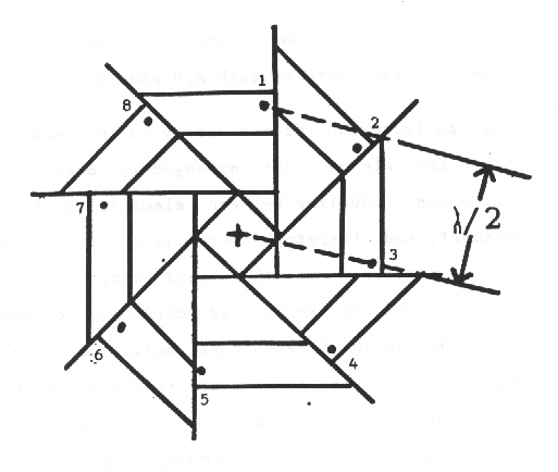
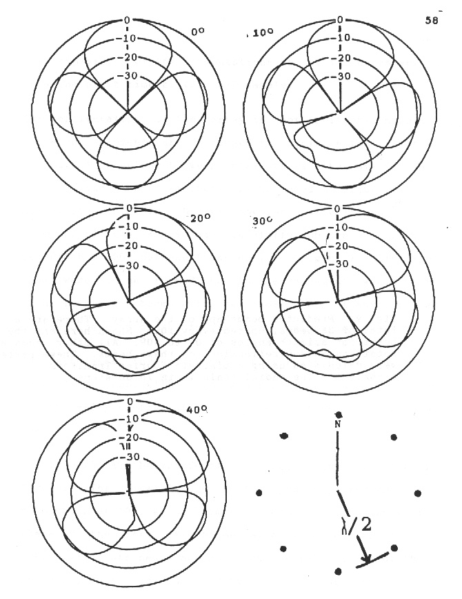
Bob Dixon's concept of an Argus radio telescope involved using a large number of small independent antenna elements, each element having its own complete receiver and analog-to-digital (A/D) converter to change the continuously varying (analog) and highly amplified output signal from the receiver into a stream of digital data that would be collected and analyzed by one or more digital computers. Although each antenna element would be independent of the others, all such elements would receive the same local oscillator (L.O.) signal(s) to downconvert the band of observing frequencies to a much lower band of frequencies so that the data could be analyzed conveniently. The common L.O. signal(s) to all receivers allows the phase information to be preserved; this is critical for the operation of an Argus radio telescope. Another important concept of an Argus array is the use of physically small antenna elements so that the beam pattern covers the entire visible hemisphere. This allows an Argus to 'see' the entire visible sky at once and to permit the use of either short integration times to catch transient events (but doing so for an observing period of many hours) or else very long integration times to recover signals buried in the noise. During discussions between Jim Bolinger and Bob Dixon, it was decided that Jim should build the prototype of a 'radio camera'; the term 'Argus' was not yet in common use, although the concepts of the 'radio camera' were essentially the same as those of 'Argus'. This prototype was to serve as a 'proof of concept' instrument, and indeed it did.
Jim states the purpose of his thesis as follows:
"The purpose of this paper is to explore the possibility of applying modern signal processing and beamforming theory to the construction of a large unfilled aperture antenna, which would be capable of forming many beams simultaneously; thereby completely eliminating the look discrimination problem and permitting transient events to be easily detected. Such a system would be capable of forming a near real-time image of the radio sky, hence the term 'Radio Camera'. Other advantages include very long signal integration time, up to 12 hours, and increased immunity to interference compared to a single antenna, which is an inherent characteristic of phased arrays due to the noise being noncoherent at each element, with respect to the signal. Also, once the signals are digitized it would be possible to compensate for receiver differences and array imperfections, thereby obtaining a 'perfect' system over a very wide bandwidth. By use of a Fourier transform, or similar process, the spectrum of the signals may be derived allowing the full signal characteristics to be studied." Jim's comment above about the integration time being up to 12 hours needs to be clarified. Depending on the latitude of the observatory and the declination of the celestial radio source, the integration time per day could be anything in the range from 0 hours to 24 hours, neglecting atmospheric effects. For example, for an observatory in the northern hemisphere, sources near the south celestial pole will never rise above the horizon, sources on the equator will be visible for 12 hours, and sources near the north celestial pole will be visible all the time (i.e., for 24 hours every day). Jim covers the theory of beamforming and fundamentals of sampling theory; they will not be covered here as they are outside the scope of this article. Before Jim describes the prototype radio camera, he lists the following five design criteria (listed in order of decreasing significance):
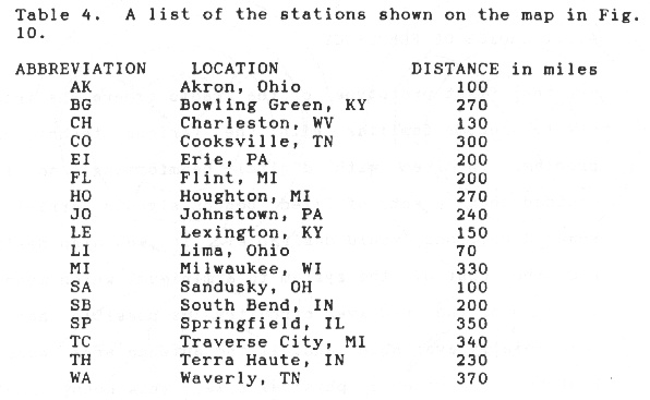
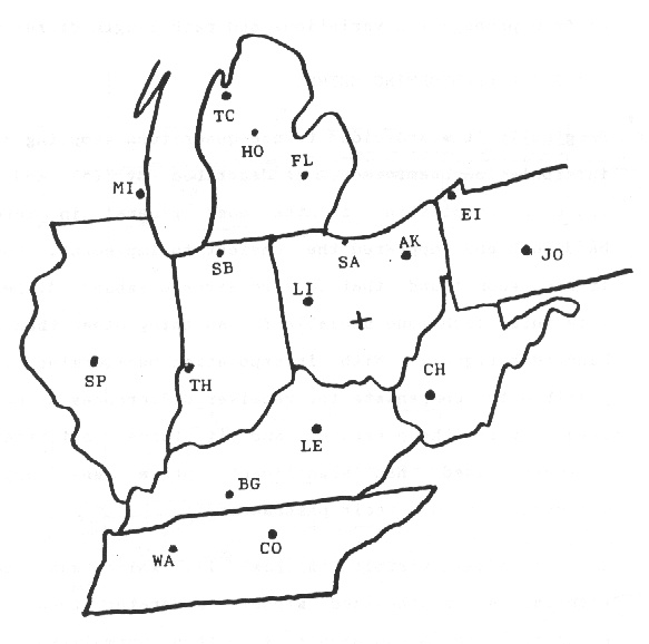
Jim decided that by using a fixed frequency and observing a set of fixed beacon signals arriving from known directions, the cost of the system could be kept to a minimum. After monitoring several frequencies, he decided to use 162.400 MHz, one of seven frequencies allocated to the National Weather Service weather radio stations.
Jim next describes the hardware and the computer software used. Discussion of these is beyond the scope of this article.
In conclusion, Jim Bolinger's Radio Camera was an excellent prototype of an Argus-type radio telescope. It accomplished 'proof of concept', at least for some of the concepts. One area that it was not able to test was a 2-dimensional directionality (i.e., both azimuth and altitude, or the celestial coordinates of right ascension and declination). However, given the limitations in computing power and electronic hardware (and money) at the time, Jim's work was well worthwhile. |
|